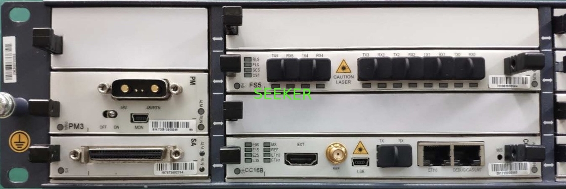
Baseband unit in BS8900A is responsible for processing the baseband signals.
Figure 2-5 Baseband Unit of BS8900A
The Baseband unit consists of control & clock board, fabric switch board, basebandprocessing board, site alarm board (optional), site alarm extension board (optional),Tower mounted Amplifier control Module (optional), power module, and fan module.
Table 2-1 Board List of Baseband Unit
Control & Clock Board (CC)
CC is control & clock board, used for control and management of baseband unit,providing Ethernet and system clock. The CC panel is illustrated in the following figure
Figure 2-6 CC Panel
Description of CC panel interfaces is shown in the following table.
Table 2-2 CC Panel Interfaces
Baseband Processing Board
There are 4 types of base band processing board in order to meet different application requirements:1. UBPGUBPG is the GSM baseband processing board. It processes the physical layer protocoland frame protocol specified by 3GPP. UBPG panel is illustrated in the following figure.Figure 2-7 UBPG Panel
2. UBPG2UBPG2 is another type of GSM baseband processing board. It provides the samefunctionalities as UBPG, and has 3 CPRI interface used for RRU remote connection. Thefigure below shows the UBPG2 panel.Figure 2-8 UBPG2 Panel
3. BPCBPC is the UMTS baseband processing board. It processes the physical layer protocoland frame protocol specified by 3GPP. BPC panel is illustrated in the following figure.
Fabric Switch Board (FS)
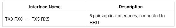
FS is fabric switch board which provides baseband optical interface between BBU andRRU and processes the IQ signal. FS panel is illustrated in the following figure.
Description of FS panel interfaces is shown in the following table.
Interface Board
1. Site Alarm Board (SA)SA/SE is a site alarm board, illustrated in the following figure.
Description of SA panel interface is shown in the following table.
2. Site alarm Extension Board (SE)SE is site alarm extension board, and shares the bottom-right slot with Basebandprocessing board. It is used to extend the port number if SA cannot fulfill therequirements. The SE panel is illustrated in the following figure.
Description of SE panel interfaces is shown in the following table.
Tower mounted Amplifier control Module (TAM)
TAM is used for tower mounted amplifier control when TMA is needed. Panel of TAM isshown as following figure
Description of the Interfaces on the TAM panel is shown in the table below.
Power Module (PM)
PM is the power module, illustrated in the following figure.
Description of PM panel interface is shown in the following table.
Fan Array Module (FAM)
FAM is fan array module which panel is illustrated in the following figure

 Your message must be between 20-3,000 characters!